By Alex DeTrano, Jason Royes, and Matthew Valites.
Executive summary Modern automobiles contain hundreds of sensors and mechanics that communicate via computers to understand their surrounding environment. Those components provide real-time information to drivers, connect the vehicle to a global network, and in some cases use that telemetry to automatically drive the vehicle. Like any computer, those in vehicles are susceptible to threats, such as vulnerabilities in software, abuse via physical-access, or even allowing remote control of the vehicle, as recently demonstrated byWired and a DARPA-funded team of researchers.
Allied Market Research estimates the global connected car market to exceed $225 billion by 2025. To help secure this emerging technology, Cisco has dedicated resources for automobile security. The Customer Experience Assessment & Penetration Team (CX APT) represents the integration of experts from the NDS, Neohapsis, and Portcullis acquisitions. This team provides a variety of security assessment and attack simulation services to customers around the globe (more infohere). CX APT specializes in identifying vulnerabilities in connected vehicle components.
During a recent engagement, the Connected Vehicle Security practice identified a gap in tooling for automobile security assessments. With ease-of-use, modern car computing requirements, and affordability as motivating factors, the Connected Vehicle Security practice has built and is open-sourcing a hardware tool called "4CAN" with accompanying software, for the benefit of all automobile security researchers. We hope 4CAN will give researchers and car manufacturers the ability to test their on-board computers for potential vulnerabilities, making the vehicles safer and more secure for drivers before they even leave the lot.
What does a car's network look like? Before jumping into the 4CAN hardware module itself, let's start with some automobile basics. For a modern vehicle to operate effectively, its network of hundreds of sensors and computers must communicate with each other. While vehicles and components employ Wi-Fi, Bluetooth, and cellular communication protocols, the backbone of a vehicle's network is a Controller Area Network (CAN), also referred to as the "CAN bus."
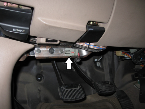
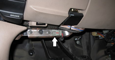
Access to the CAN bus from a physical perspective is typically via an OBD2 connector, often located on the driver-side lower dash, though it can sometimes also be accessed by removing side mirrors or external lights. Compromising the CAN bus can lead to total control of the vehicle, making it a prime target for pen testers and malicious attackers. Often, attacks against peripheral components such as Wi-Fi or LTE are ultimately an attempt to gain access to the CAN bus.
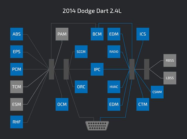
CAN Bus background A typical vehicle's CAN bus is shown below. In a secure configuration, the critical components such as airbags and brakes communicate on separate CAN buses from the non-critical components, such as the radio or interior lights. Pen testers and attackers with access to the CAN bus test for this separation of services looking for insecurely configured vehicles.
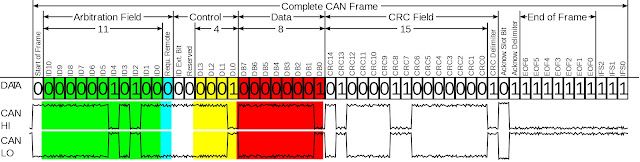
The CAN bus is a two-wire multi-master serial bus. Each device connected to the CAN bus is called a "node" or Electronic Control Unit (ECU). When a device sends out a message, or CAN frame, that message is broadcast to the CAN bus and received by every node. When two nodes broadcast a CAN frame at the same time, the arbitration ID, a type of unique node identifier on every CAN frame, determines message priority. The CAN frame with the lower arbitration ID takes priority over the higher arbitration ID.
Electrically, the CAN bus uses differential signaling as a means to reduce noise and interference. There is CAN-HI and a CAN-LO signal, and the two signals are inverse from each other. The bus also has a 120 ohm characteristic bus impedance. When performing a CAN-in-the-middle, the bus must be terminated with a 120 ohm resistor. The image shown below is fromWikipedia, which has an excellent overview of the CAN bus if you're interested in more detailed information.
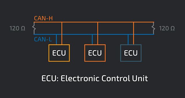
Single CAN bus with multiple nodes
The simplest implementation of an automobile's network uses a single CAN bus. An example with 3 nodes is shown below. All connected nodes will see every CAN message published to the CAN bus. There is no ability to separate critical from non-critical nodes.
Multiple CAN buses with a gateway A typical vehicle setup has multiple CAN buses combined with a gateway to arbitrate access between the CAN buses. This gateway acts as a firewall and can check CAN IDs to determine if the message should be allowed to traverse CAN buses. In this way, critical ECUs can be isolated from non-critical ECUs.
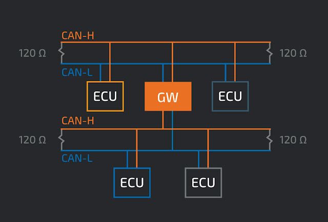
The vehicles that we have been testing have 4 CAN buses inside, all of which are connected to the gateway. The architecture looks something like this:
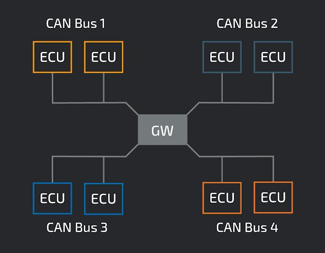
The security of each ECU on the bus is partly dependent on the gateway's ability to segregate traffic. Testing the gateway involves sending and looking for messages allowed to traverse disparate CAN buses. On four-bus systems, this test requires pen testers can access the four buses simultaneously.
Existing solutions
Several devices exist that allow testing of the CAN bus. Most of the devices use theMCP2515 CAN controller, which provides a serial peripheral interface (SPI) to connect with a microcontroller, and aMCP2551 CAN TransceiverorNXP TJA1050 CAN Transceiver, which generates and receives the electrical signals on the physical CAN bus. This table describes some of the CAN hacking solutions currently available on the market.
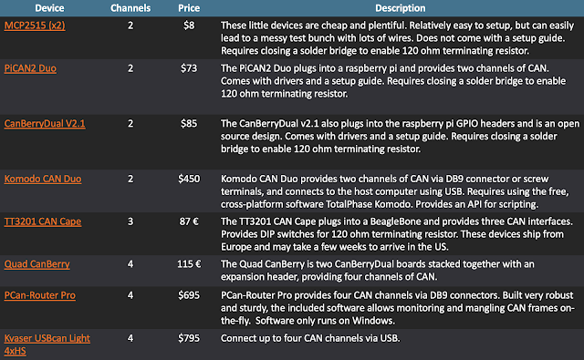
Each device has its pros and cons, but none completely met our needs of being easy to use, allowing access four buses, and doing so at an affordable price point. Here's how the currently available devices align with our needs.
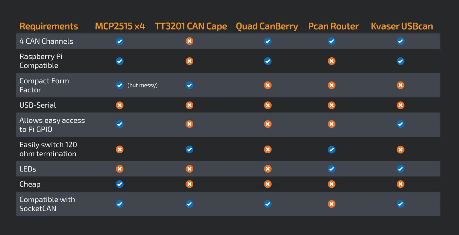
In the absence of a compatible device we set out to solve this problem, doing so with the following technical motivators:
- Raspberry Pi compatible
- Easily enable or disable 120 ohm bus terminating resistors
- Natively supported by SocketCAN for easy Linux integration
- Inexpensive
Our Solution
We call the solution "4CAN," and designed it with the following goals in mind:
- Validating communication policy for intra-CAN bus communication.
- Fuzzing (sending randomized payloads) to components to identify vulnerabilities.
- Exploring the CAN commands used to control/interact with the vehicle.
- Simplify our testbench setup to keep everything organized and in sync.
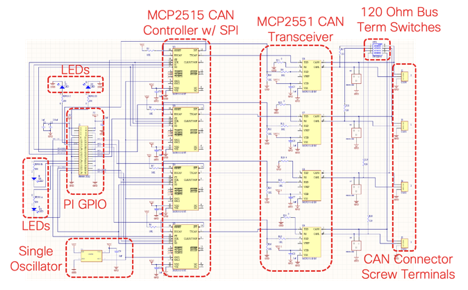
Design George Tarnovsky, a member of CX APT, is the originator or the 4CAN's design. The Raspberry Pi contains five hardware SPI channels so we decided to use the MCP2515 CAN Controller since it could interface with the Pi via SPI. We added a four-port DIP switch instead of physical jumpers or a solder bridge to easily enable the 120 ohm bus terminating resistors. The MCP2551 CAN transceiver was used as the CAN transceiver.
The high-level design is described in the below schematic, the more detailed version of which can be found here.
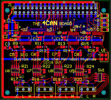
PCB layout To be as compatible as possible, we aimed to conform to theRaspberry Pi HAT specification as closely as possible. The HAT spec limits the hardware dimensions, requiring us to use creative solutions to pack all the components on the board. Since we did not include an EEPROM and did not leave a cutout for the camera connector, the module is not HAT compliant per spec. These were conscious design decisions, since we will not be using a camera add-on and do not make use of the EEPROM.
All components are surface mounted, using the smallest component sizes we could find to minimize space on the board. The only exception to using the smallest components is the USB-UART connection. Instead of adding all the components ourselves, we went with a premade board containing all the circuitry. This board sits on top of the 4CAN. A resistor pack further reduces part-count and has a smaller footprint than four individual resistors. Rather than drive all four CAN controllers with individual crystal oscillators, we opted to use just one. This can introduce clock skew, because each component receives the clock in serial, rather than in parallel at the same time. To limit the effect of clock skew, we kept the clock lines as short as possible. In order to keep costs down, we used a 2-layer PCB design. While this limits routing options, the cost is significantly cheaper than a board with more layers. We also added the standard 40-pin GPIO header, so that the remaining GPIO can be used.
The final layout is shown below.
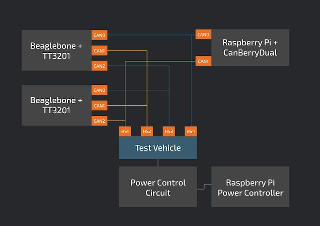
Before and after
Before In order to test four CAN buses simultaneously, we required three CAN devices. Two TT3201 three-channel CAN Capes attached to Beaglebones, and one CanBerryDual attached to a Raspberry Pi. We also have another Raspberry Pi to remotely control the test vehicle. With this configuration, we can test sending CAN frames between any two combinations of CAN channels. Although this setup works, it is a bit unwieldy, requiring lots of wires making connection tracking and test aggregation difficult.
AfterUsing 4CAN, the test bench setup is vastly simplified. With a single Raspberry Pi, we can simultaneously test four CAN channels, and since the 4CAN exposes the entire 40-pin GPIO header, we can remotely control the test vehicle.
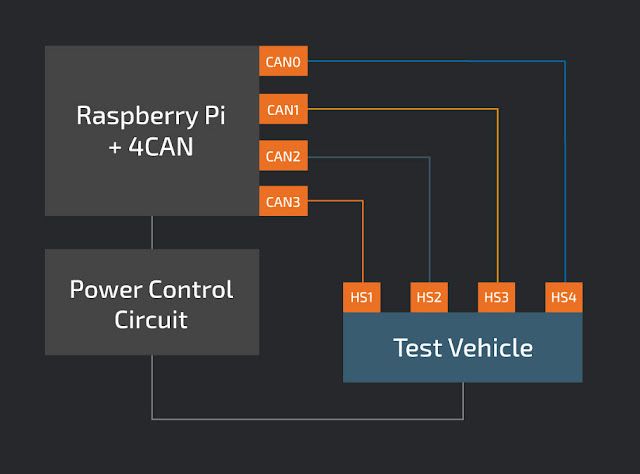
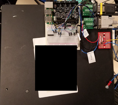
The simplicity of using 4CAN is easily observable on the physical test bench.
Before 4CAN:
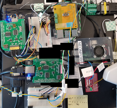
Using 4CAN: